Power Systems
by Steve Gillett
For many years the NEONS kept their head in the
sand when it came to DCC. Because very few of us had decoder equipped engines we both resisted and avoided it.
However, as DCC became more and more commonplace and our members began to acquire and/or convert some of their
locomotives to DCC, it became clear we needed get with the program, move into the 21st century and get some
of them thar new-fangled DCC thing-a-ma-jigs for both our permanent layout and our show layout.
Our first decision was to select Digitrax as the manufacturer of choice since
their equipment was used at most shows we attend. NEONS has a very large
travelling layout plus a small, 8-module layout that is semi-permanently set up at sponsor's store,
Challenger N-Scale Hobbies.
The store layout benefits both our club and
our sponsor since it allows club members to run trains whenever the store is
open and provides the store with a place for customers to test new or potential
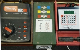
purchases. This store layout was powered by three MRC Tech II Railpower 2500
power packs (one each for the red, yellow and blue lines.) We added a Digitrax
Zephyr DCC system and built a panel with three toggle switches, thus allowing
operators to toggle between DCC and the assigned DC power pack on each of the
three lines (See Figures 1 and 1a).
Early research and experience by clubs across the country led to a few rules of
thumb. The first and most critical rule is a Digitrax power distribution
line should never extend more than 50’ in either direction from the power source.
The longer the distribution line, the more resistance there is, and the more the
signals degrade. Because our show layout loop is usually between 150’ and 240’
long, we decided to break our layout/loop into three blocks and locate a power
supply near the center of each block so that the distribution lines never exceed
the 50’ guideline. We initially installed Digitrax equipment only on the red line
of our travel layout so we could tie into the Red Line Route™. The other two lines
remained powered with Aristo-Craft wireless DC throttles. Eventually, the
flexibility we became used to on our store layout led us to develop a similar
system for shows.
Since we nearly always link up with other clubs at shows to form a multi-loop
layout using the Red Line Route™ format (which is exclusively Digitrax DCC), we only
need to offer the choice of DC / DCC on the yellow and blue lines. (The NEONS do
not have the mountain line on any of our modules.)
Using the
North Raleigh Model Railroad Club's design as
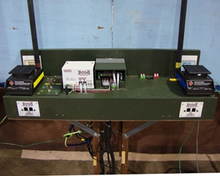
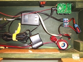
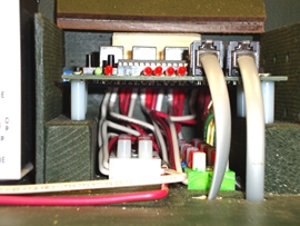
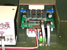
a base, we constructed three custom power boxes, each with a Digitrax 8 amp DB200
booster, a Digitrax PM42 to split the DCC power to the Red, Yellow, Blue and Green
lines, two UP-5 loconet interconnects, and two Aristo-Craft DC analog power receivers
and antennas that receive signals from our Aristo-Craft wireless remote throttles.
Each box is powered by a Digitrax 2012 20-amp power supply that feeds the Digitrax
and the Aristo-Craft units and also has two wall warts, one for the PM42 and one for
the UP-5s. In order to protect the power equipment and all engines on the layout, each
of the three units in each box (two Aristo-Craft receivers and one Digitrax DB200) is
fused on both the inlet and outlet side. We keep a large supply of fuses just in case!
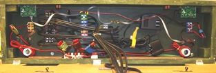
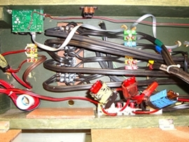
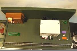
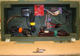
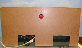
(Figures 2-8 and Diagrams 1-4).
Diagram 1 -- Power Box Schematics - Top View
Diagram 2 -- Power Box Schematics - Front View
Diagram 3 -- Power Box Schematics - Bottom View
Diagram 4 -- Power Box Schematics - Doors
Diagram 2 -- Power Box Schematics - Front View
Diagram 3 -- Power Box Schematics - Bottom View
Diagram 4 -- Power Box Schematics - Doors
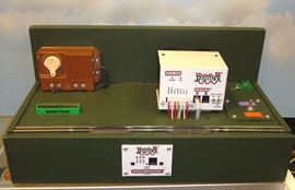
The DCC equipment in all three power boxes is controlled by a Master Command Station.
This unit contains a Digitrax DCS200 8-amp command station, an LNRP loconet repeater and our
old Aristo-Craft 10 amp power supply. It does not power any track, but functions as the brains
of the system. Its only connection to the layout is through the Loconet bus and a ground wire.
If we link our loop with others to form a multi-loop layout, we can either use our Master Command
station, or disconnect it from the loconet and use the host club’s equipment for that task.
The Master Command Station also contains a programming/test track and a wheel cleaning tool.
By toggling a switch, the 17” long track works as a programming track or a test track.
Even though the DCS200 doesn’t power a block of track, we use an 8-amp unit here so that
if one of the boosters fails, the DCS200 can do double duty as the Master Command Station
and supply power to one block. An old-style beginner transformer powers the wheel cleaning
tool. (Fig 9-12 and Diagrams 5-8)
Diagram 5 -- Master Command Station Schematics - Top View
Diagram 6 -- Master Command Station Schematics - Front View
Diagram 7 -- Master Command Station Schematics - Bottom View
Diagram 8 -- Master Command Station Schematics - Doors
Diagram 6 -- Master Command Station Schematics - Front View
Diagram 7 -- Master Command Station Schematics - Bottom View
Diagram 8 -- Master Command Station Schematics - Doors
Each power box is 9” deep and 30” long so it can be clamped on the back of any module, including a
corner module. The Master Command box is 18” long. At the back right corner of each box is a terminal
block where ground wires can be connected. (Fig 13) All equipment in each box is tied to this ground
block. We have several spools of ground wire that we use to interconnect the boxes. Even though all
four of our power supplies have a grounded 110v plug, only one is connected to the grounding system
so that there will be no possibility of a ground feedback loop.

