NEONS Power Systems
by Steve Gillett
For many years the N-Trak club to which I belong (
NEONS, the North East
Oklahoma N-Scalers) kept its head in the sand when it came to DCC.
Because very few of us had decoder equipped engines, we both resisted and
avoided it. However, as DCC became more and more commonplace and our members
began to acquire and/or convert some of their locomotives to DCC, it became
clear that we needed get with the program, move into the 21st century and get
some of them thar new-fangled DCC thing-a-ma-jigs for both our permanent layout
and our show layout.
Our first decision was to select Digitrax as the manufacturer of choice since
their equipment was used at most shows we attend.
NEONS has a very large
travelling layout plus a small, 8-module layout that is semi-permanently set up at our
sponsor’s train store. The store layout benefits both our club and
our sponsor since it allows club members to run trains whenever the store is
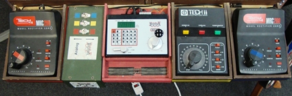
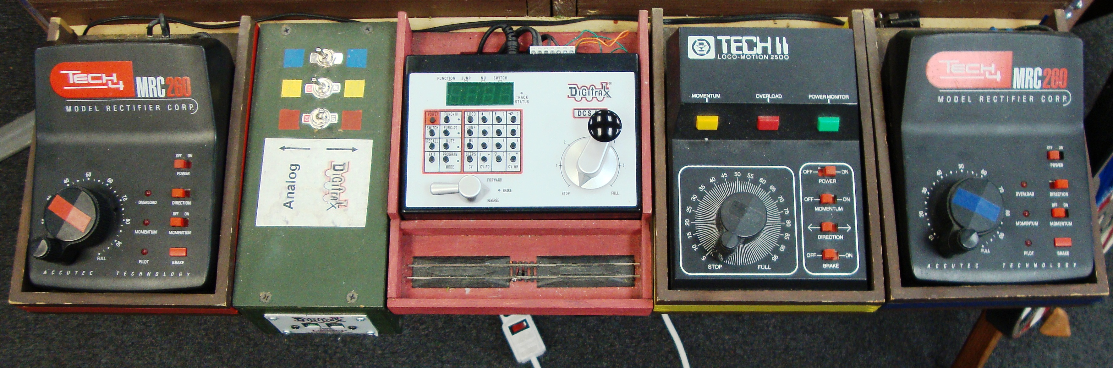
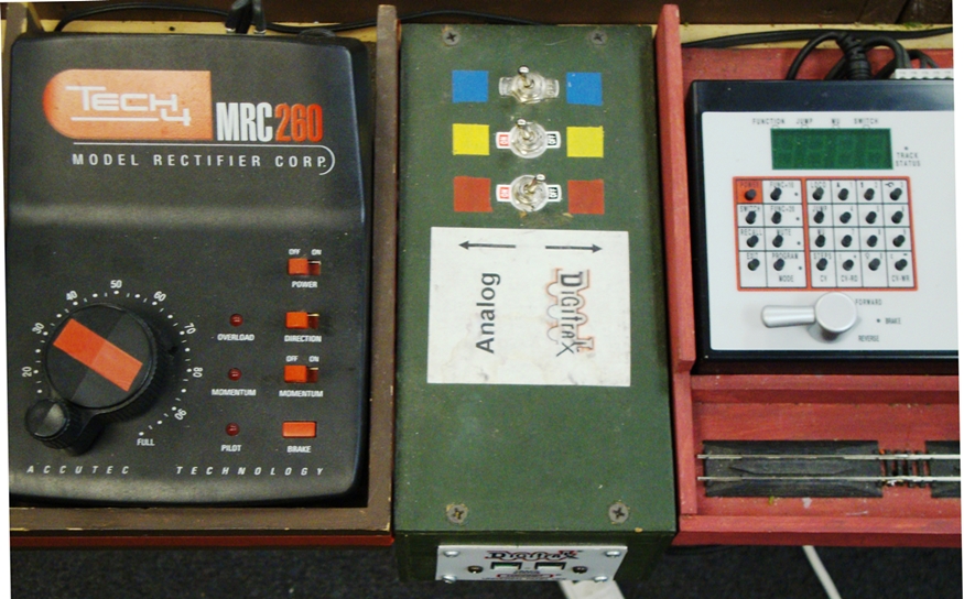
Figure 1 - Power System on Store Layout
open and provides the store with a place for customers to test new or potential
purchases. This store layout was powered by three MRC Tech II Railpower 2500
power packs (one each for the red, yellow and blue lines.) We added a Digitrax
Zephyr DCC system and built a panel with three toggle switches, thus allowing
operators to toggle between DCC and the assigned DC power pack on each of the
three lines (See Figures 1 and 1a).
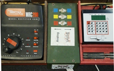
Figure 1a - Power System on Store Layout
Early research and experience by clubs across the country led to a few rules of
thumb. The first and most critical rule is that a Digitrax power distribution
line should never extend more than 50’ in either direction from the power source.
The longer the distribution line, the more resistance there is, and the more the
signals degrade. Because our show layout loop is usually between 150’ and 240’
long, we decided to break our layout/loop into three blocks and locate a power
supply near the center of each block so that the distribution lines never exceed
the 50’ guideline. We initially installed Digitrax equipment only on the red line
of our travel layout so we could tie into the Red Line Route™. The other two lines
remained powered with Aristo-Craft wireless DC throttles. Eventually, the
flexibility we became used to on our store layout led us to develop a similar
system for shows.
Since we nearly always link up with other clubs at shows to form a multi-loop
layout using the Red Line Route™ format (which is exclusively Digitrax DCC), we only
need to offer the choice of DC / DCC on the yellow and blue lines. (The
NEONS do
not have the mountain line on any of our modules.)
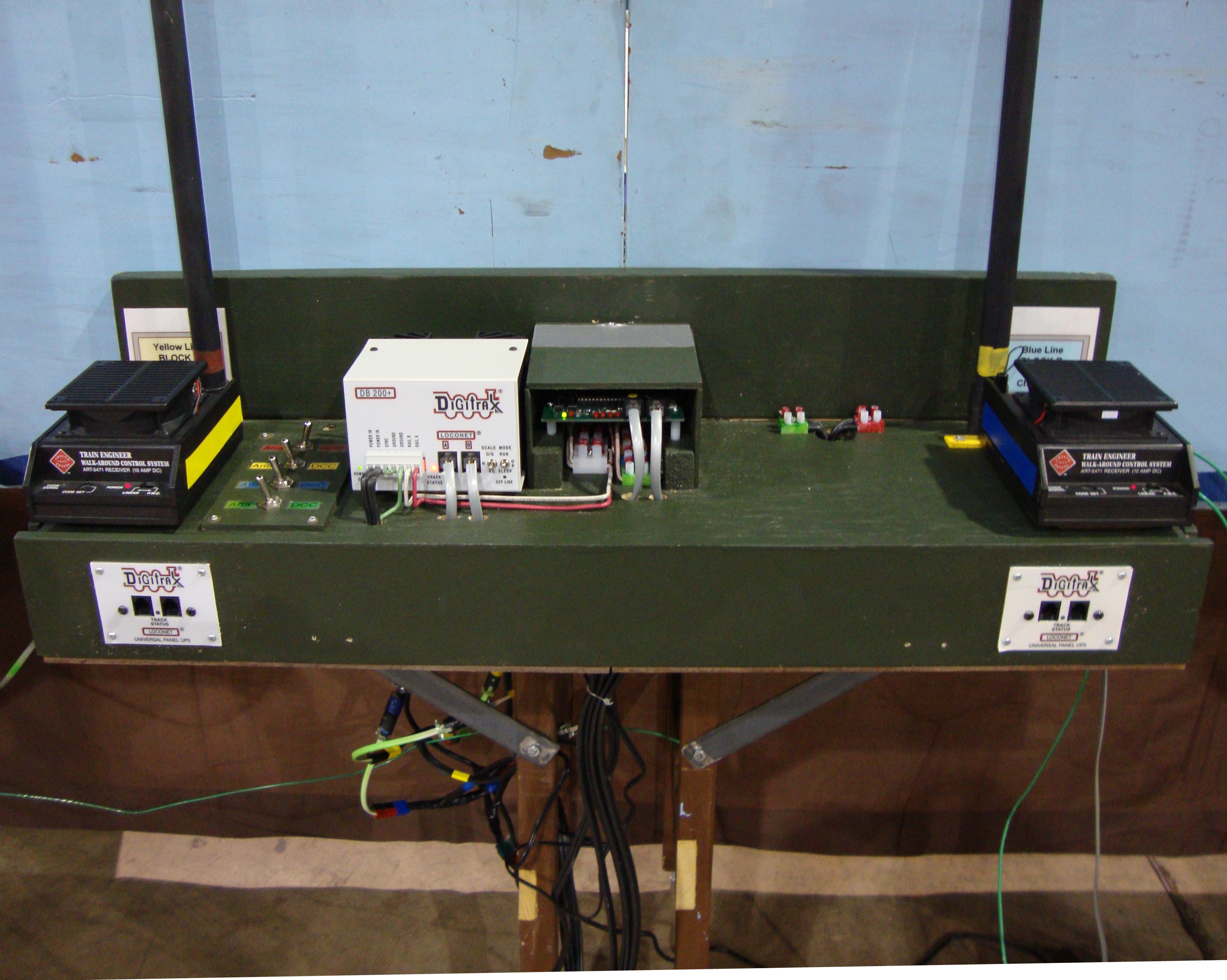
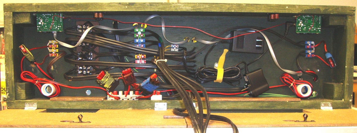
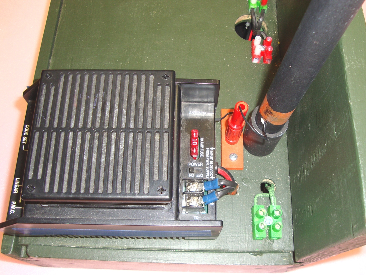
Figure 2 - Power Box Top & Front View
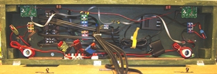
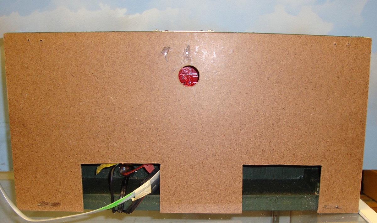
Figure 3 - Power Box Bottom View
Using the
North Raleigh Model Railroad Club's design as
a base, we constructed three custom power boxes, each with a Digitrax 8 amp DB200
booster, a Digitrax PM42 to split the DCC power to the Red, Yellow, Blue and Green
lines, two UP-5 loconet interconnects, and two Aristo-Craft DC analog power receivers
and antennas that receive signals from our Aristo-Craft wireless remote throttles.
Each box is powered by a Digitrax 2012 20-amp power supply that feeds the Digitrax
and the Aristo-Craft units and also has two wall warts, one for the PM42 and one for
the UP-5s. In order to protect the power equipment and all engines on the layout, each
of the three units in each box (two Aristo-Craft receivers and one Digitrax DB200) is
fused on both the inlet and outlet side. We keep a large supply of fuses just in case!
(Figures 2-8 and Diagrams 1-4).

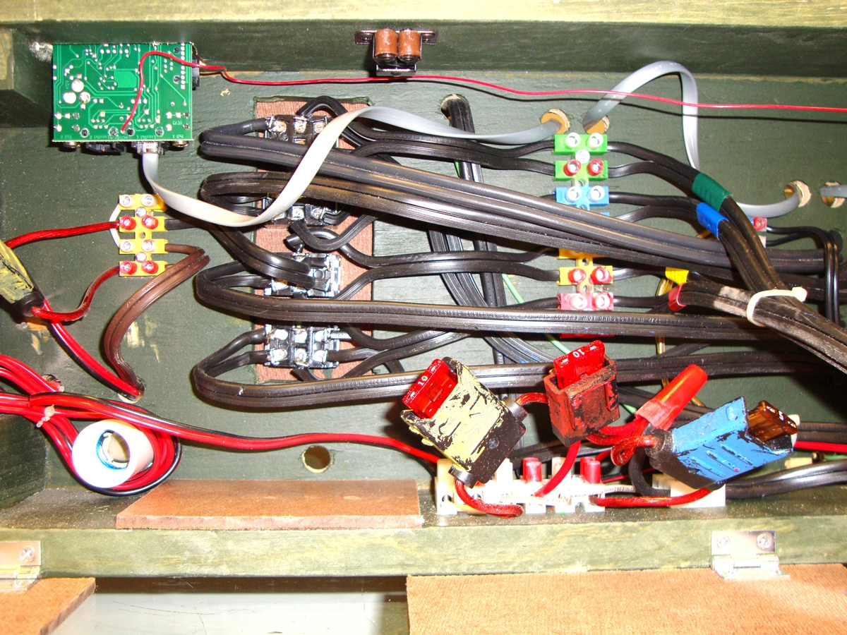
Figure 4 - Power Box
Bottom Left Side
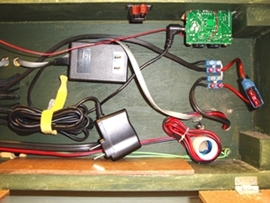
Figure 5 - Power Box
Bottom - Right Side
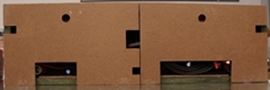
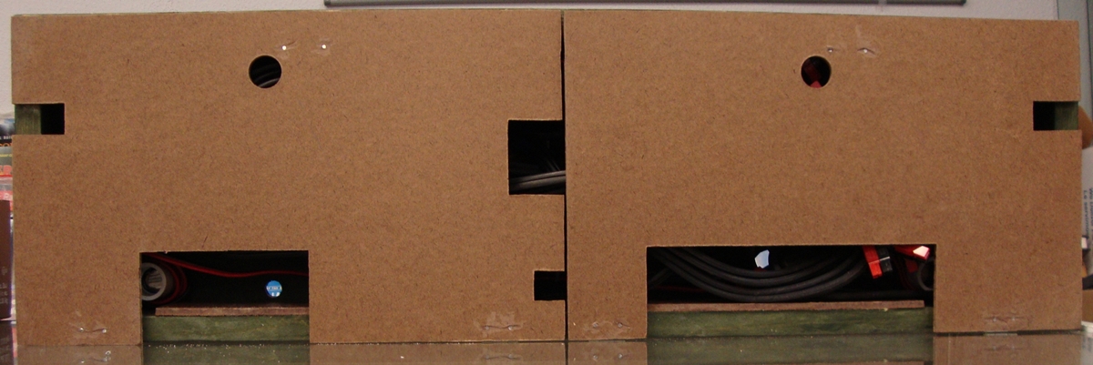
Figure 6 - Power Box
Bottom - Doors Closed

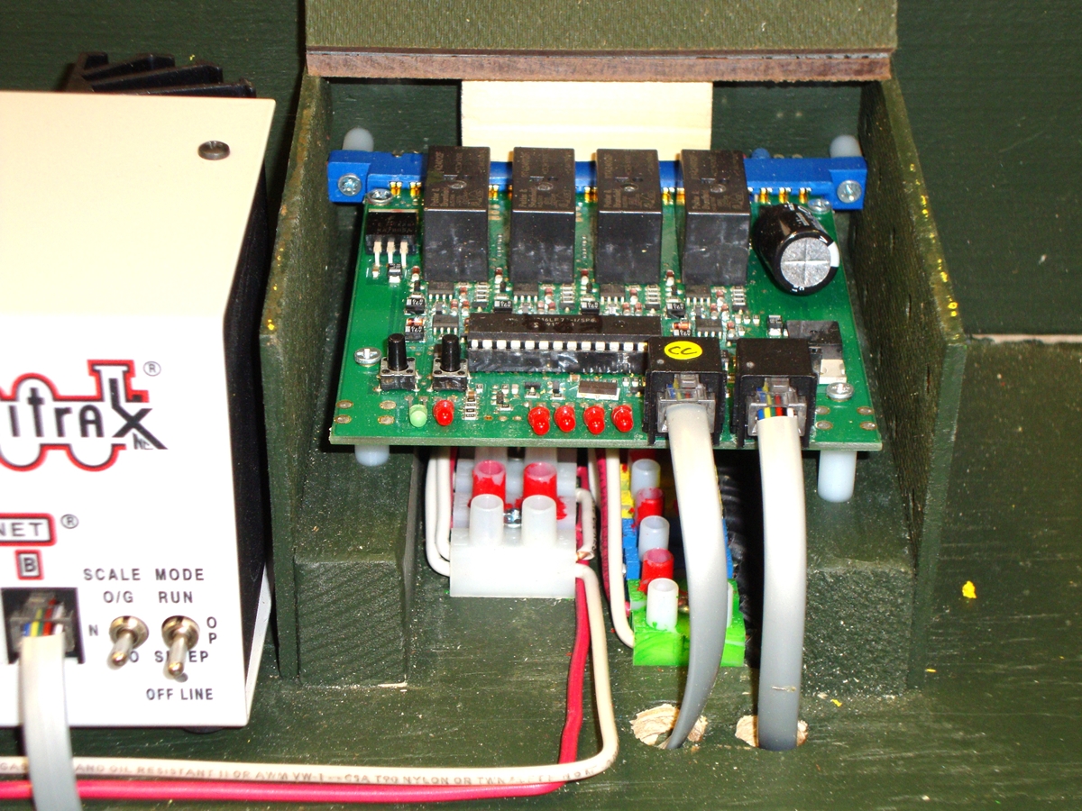
Figure 7 - Power Box
PM42 - Front View
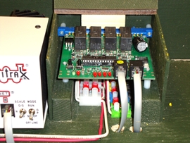
Figure 8 - Power Box
PM42 - Top View

Figure 9 - Master Command Station
Front View
The DCC equipment in all three power boxes is controlled by a Master Command Station.
This unit contains a Digitrax DCS200 8-amp command station, an LNRP loconet repeater and our
old Aristo-Craft 10 amp power supply. It does not power any track, but functions as the brains
of the system. Its only connection to the layout is through the Loconet bus and a ground wire.
If we link our loop with others to form a multi-loop layout, we can either use our Master Command
station, or disconnect it from the loconet and use the host club’s equipment for that task.
The Master Command Station also contains a programming/test track and a wheel cleaning tool.
By toggling a switch, the 17” long track works as a programming track or a test track.
Even though the DCS200 doesn’t power a block of track, we use an 8-amp unit here so that
if one of the boosters fails, the DCS200 can do double duty as the Master Command Station
and supply power to one block. An old-style beginner transformer powers the wheel cleaning
tool. (Fig 9-12 and Diagrams 5-8)
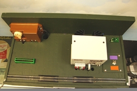
Figure 10 - Master Command Station
Top View
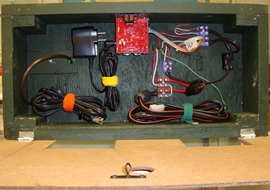
Fig 11 - Master Command Station
Bottom View
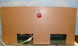
Figure 12 - Master Command Station
Bottom - Door Closed

Figure 13 -- Ground Connection and
Aristo Antenna Connection
Each power box is 9” deep and 30” long so it can be clamped on the back of any module,
including a corner module. The Master Command box is 18” long. At the back right corner
of each box is a terminal block where ground wires can be connected. (Fig 13)
All equipment in each box is tied to this ground block. We have several spools of ground
wire that we use to interconnect the boxes. Even though all four of our power supplies have
a grounded 110v plug, only one is connected to the grounding system so that there will be no
possibility of a ground feedback loop.
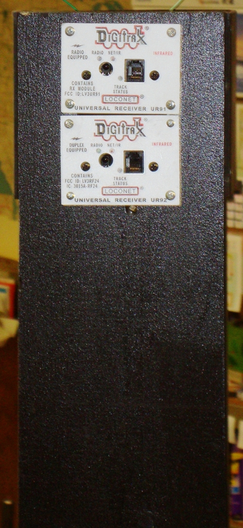
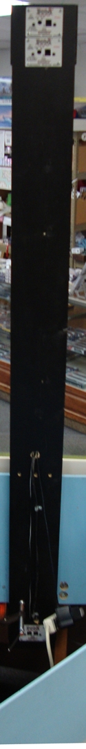
Our radio tower has a Digitrax UR91 Simplex radio receiver and a UR92 Duplex radio receiver to
allow wireless control of our Digitrax equipment. The receivers are mounted at the top of the
tower so that they are over 8’ above ground to minimize interference and maximize range.
(Fig 14 & 14a)
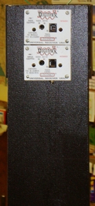
Figure 14
Radio Tower
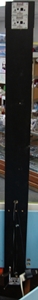
Figure 14a
Radio Tower
There is a separate antenna for each of the Aristo-Craft receivers mounted on
the power boxes next to the receiver. Each antenna wire is threaded inside a piece of ½” PVC
that sits in a ½” PVC collar attached to the boxes. The wire is connected with banana plugs.
The PVC tubes are painted black and look like smokestacks. (Fig 13)
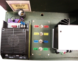
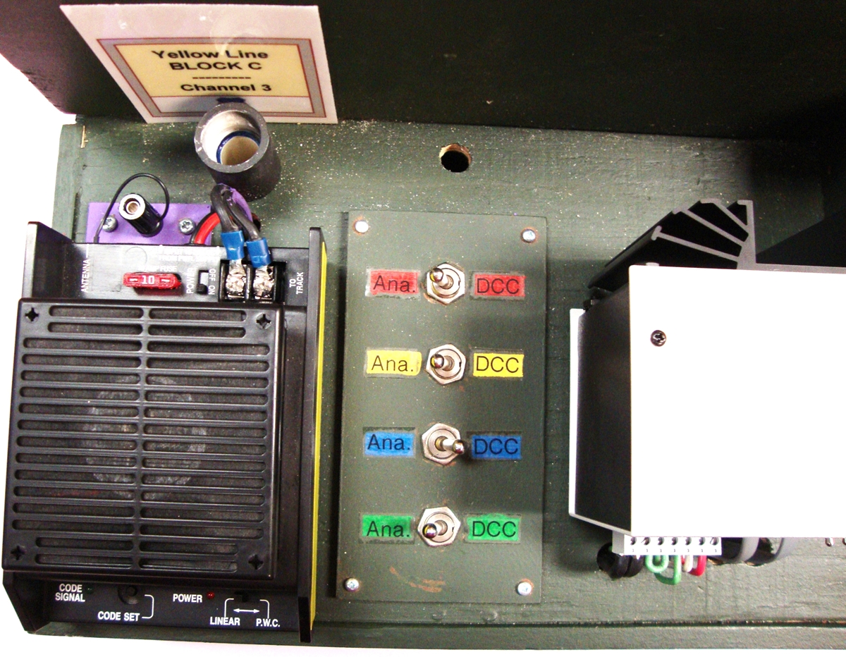
Figure 15 -- Toggle Switches
Each line (Red, Yellow, Blue and Green) can be switched between DC and DCC with a toggle switch. (Fig 15)
One of the two Aristo-Craft receivers is assigned to the Yellow line and the other to the Blue
line. Access jacks are in place to attach a DC power supply for the Red Line and one for the Green
line if needed. We rarely do that because we always designate the Red line as DCC and, since we
don’t have a mountain line, the green line is normally used as a back-up or to power isolated
sidings that have switching operations.
Home
Top of Page
Another rule of thumb that became an N-Trak recommended practice was to upgrade all the power
distribution bus lines under each module from 18 gauge wire with Cinch-Jones connectors to 12
gauge wire with Anderson 30 amp Power-Pole connectors. The
NEONS implemented this
upgrade on all of our modules. (Diagram 9)
The three power boxes give us six Aristo-Craft receivers, three each for the Yellow and
Blue lines. All six receivers are set to the same frequency. Depending on the desires of the
operators, we either set each of the three receivers on a line to a different channel so the
operator must change channels as his/her train moves from block to block, allowing him/her to
operate two trains at a time, or we set all three receivers on the line to one channel allowing
only one train at a time but eliminating the need to constantly change channels.
Although this Aristo-Craft operating procedure looked simple on paper, it quickly became a serious
problem in practice. At times, a train uncouples. When this happens, the operator reverses power,
backs the train up, reconnects, reverses power again, and continues on. Unfortunately, since our
power boxes are distributed around the layout, all three Aristo-Craft receivers serving that line
don’t always receive and process the power reversal signal. This sometimes results in reversed
polarity at a block boundary and when an engine crosses that boundary, there is a short, the train
won’t move, and sometimes wheel-sets are melted (which is another reason for the fuses!) Also,
when more than one train is running on a DC line, there can be other problems. Not all engines
require the same amount of power to move at a certain speed. As a train enters a block, the
operator must switch his/her throttle to the new block and adjust the power level so the train
maintains the proper speed. Failure to do this will cause a train to either slow down or speed
up at each block boundary depending on what the power requirements of the train in front required.
At a recent trains show, we discussed our DC and DCC problems with our favorite Digitrax Booth
Buffalo. After a thorough review, it was suggested that we really didn’t need to break our loop
into the three blocks. Since all of the
NEONS modules have 12 gauge power bus wires with
Anderson 30-amp Power-Pole connecters and since we use Digitrax DB200 8-amp boosters, the line
resistance is minimized and the power is maximized. The previously mentioned guideline that a
power distribution line should extend a maximum of 50’ in each direction from the booster before
it will suffer too much power loss was based on a system with 18 gauge wire, Cinch-Jones connectors
and a 5 amp unit. With our equipment, we have the choice of connecting each DCC booster to power
three or four lines for 50’ in each direction, or a single line for at least 100’ in each direction,
and even further if it is a continuous loop.
By simply designating each of the three power boxes to serve a single line around the entire loop,
one for the red, one for the yellow and one for the blue, this new format was implemented. The
only modification we had to make was to increase the maximum power allowance on each sub of the
PM42s. This also solves our DC problems since, in this arrangement, only one Aristo-Craft unit
serves each line. Now, when two trains are running on a DC powered line, the faster train will
occasionally have to divert to siding that has a power on/off switch and wait until the slower
train gains a little ground.
Our DCC problems also included low voltage on our Loconet system. When we counted them up, we
realized that we had over 20 UP-5s connected to the Loconet, and none of them were powered. Our
modules do not have the white line bus so we decided that is was less expensive and less work to
purchase and install wall warts for each UP-5. That solved the Loconet problem!
All in all, our new power system is now a simple, integrated, plug and play arrangement, with
plenty of versatility that allows our members and guests to operate any train on any line,
regardless of whether or not the engine(s) is decoder equipped.
Home
Top of Page