Nested, Integral Folding Legs w/ Metal Braces
by Steve Gillett
Over the years NEONS has developed a detailed plan for the design and construction of N-Track modules that includes
permanently mounted, folding module legs
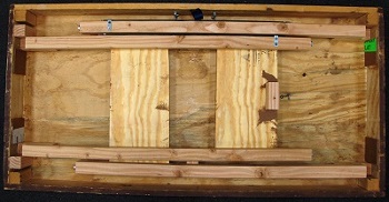
(4' module construction diagram). These legs are built as two 2-leg pairs
that fold up inside the module base. One leg pair nests between the other pair, leaving 1½” of clearance between
the folded legs and the bottom of the module deck. This clearance allows room for Digitrax UP-5s, turnout switch
machines such as Tortoises, wiring harnesses, power strips and other under-the-deck equipment. When the legs are
collapsed and secured they fit completely inside the frame with nothing hanging below the base of the fascia boards.
The challenge is not only to have legs that fold up and are permanently attached, but to make the legs adequately sturdy,
stable, easy to erect and simple to collapse and secure. This leg design can be retro-fitted onto existing modules with
reasonable ease. All that is required to achieve this goal is a little hardware and some 2” x 2” dimensional lumber.
Nearly all our modules are built with a ½” plywood deck screwed to a frame made with 1x4s, and our legs are
built from 2x2 dimensional lumber. (We actually rip our 2x2s from 2x4s since we have a hard time finding good,
straight, un-warped 2x2s at a reasonable price.) As we all know, 1” x 4” boards are really ¾” x 3½” and 2” x 2”
boards are really 1½” x 1½”. So, for us the clearance between the base of the module deck and the bottom of the
frame is 3½”. The collapsed legs take up 1½” to 2” of that space leaving 1½” available for other under-the-table
items. Obviously the full 3½” space is available in the areas where there are no legs. Key features of our design
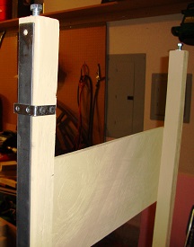
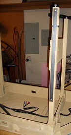
include 2’ long, semi-rigid leg braces made of 1/8” x 1” steel bar stock (Figure 1) and the snap and latch
mechanism that secures those braces to the module frame (Figure 2), thereby providing the sturdy and stable leg
assembly we desire.
Equipment, Tools & Supplies Needed:
-
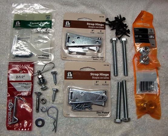
Hardware (Figure 3)
- 1 – package ½” 12-7 hitch pins (2/pkg)
- 2 – ¼” x 1½” carriage bolt
- 2 – ¼” flat washer
- 2 – ¼” lock washer
- 2 – ¼” hex nut
- 2 – ¼” x ¾” hex head wood screw
- 2 – packages 3/8” T-nuts (2/pkg)
- 4 – 3/8” x 3” full thread hex head bolt
- ½ – package 1½” “L” brackets (4/pkg)
- 1– 2½” locking hook & eye set
- 2 – package 3” strap hinges (2/pkg) (screws included)
- 1 – 1/8” x 1” x 48” steel strap
- 4 – 1¼” #6 round head wood screws (for L-brackets)
- 8 – 1¼” #6 flat head wood screws (for spreader bars)
- ? – 1¼” and 1 5/8” #6 flat head wood screws (for glue blocks and frame braces as needed)
-
Tools
- Drill motor
- Phillips head screw bit
- ¼” wood drill bit
- 5/8” spade bit
- ¼” metal drill bit
- 3/32” metal drill bit
- Drill press
- Bench grinder
- Tape measure
- Hacksaw
- 2# sledge hammer
- 7/16” box wrench or Crescent wrench
-
Supplies
- Wood glue
- Sand paper
- 3 – 8’ x 2” x 2” OR 2 – 8’ x 2” x 4” kiln dried lumber
- Scrap piece of ½” 3-ply plywood
Preparation:
- Cut the legs, glue blocks and spreader bars to the appropriate length. (Refer to measurements in 4' module construction diagram for leg length.) Sand. Drill ½” hole at least 4” into one end of each leg. Tap in 3/8” T-nuts and screw in 3/8” x 3” hex head bolts.
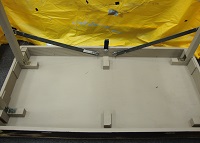
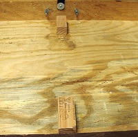
- The under-frame must be properly prepared to accept the legs. First, depending on the length of the module, one or more 2” x 2” braces must be installed from the front of the module to the back. (A 4’ module needs one brace, a 6’ or 8’ module needs two braces.) Each brace must be flush to the bottom of the module deck. The folded legs will rest against this brace. Before installing the brace, drill two ½” holes and three 5/8” holes through the brace. These holes allow wiring to pass from one side of the module to the other without being pinched by the folded legs. (Figure 4 shows how this brace can be substituted with two shorter glue blocks on retro-fit modules.)
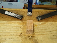
- The leg assemblies gain additional strength when two sides of each leg are against the frame. When we build our module frames, we place a 3¼” glue block in each corner to add strength where the 1” x 4” pieces meet. Next to that we glue and screw a 5” glue block that is laid horizontally and attached to the deck. When erected, the leg is flush against the 3¼” glue block on one side and against the 1” x 4” on another side and seats firmly against the horizontal glue block. When the spreader bars are attached, the legs become very sturdy from front to rear. Note that on one side of the module, the vertical glue block is 3¼” x 2” x 2” and on the other side it is 3¼” x 2” x 4”. This allows the legs on one side to nest between the legs on the other side with a ½” gap between them. That gap is where the metal braces will go. (Figures 5 & 6)
- Several major hardware chains carry the steel bar stock in 4’ and 6’ lengths. The bars can be cut to 2’ lengths with a hacksaw or a Dremel tool. Drill ¼” holes at each end of the bar and then grind both ends smooth with a bench grinder or a grinder wheel attached to a drill. (Figure 7)
- The hitch pins work best when inserted through a hole in the carriage bolt. To drill the carriage bolt, thread a nut onto the bolt, take a scrap piece of wood, lay the bolt/nut assembly on the wood and hammer it into the wood with a 2 pound sledge until it makes an impression in the wood. You now have a jig to use for drilling the bolts. Drill a 3/32” hole through the nut and the bolt then work the nut up and down the screw threads to remove all flash. The nut can then be threaded onto the next bolt to be drilled. It is best to use a drill press for this operation. (Figures 8 & 9)
Installation:
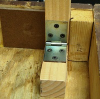
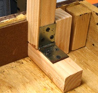
- Position a leg against the frame and the vertical glue block, then, screw the 3” hinge into the leg and into the horizontal glue block. Align the legs, then glue and screw the spreader bars into position. Be sure the spreader bars are attached to the sides of the legs that are closest to the deck. When the legs are closed, the narrower pair of legs will fold over the spreader bar of the wider pair, locking the wider leg pair in place. (Figure 10)
- Normally the metal leg braces are only installed on the rear legs but in cases where those braces would interfere with items to be clamped onto the rear of the module, the braces can be attached to the front legs instead. On extra heavy modules braces are attached to all four legs.
- Open the legs and clamp them to the frame. Place the metal brace along the leg so that one end is about ½” from the end of the leg that contains the height adjustment screw. Drill a pilot hole and attach brace to the leg at the end closest to the frame using a ¼” x ¾” hex screw. Tighten the screw snugly, but not so snug that the bar can’t be rotated down to the frame. Attach the “L” bracket that will keep the brace from falling down when the legs are in the storage position. Remember that you’re working upside down so when you attach the bracket, the screws will be on the side that will eventually be on the bottom when the unit is turned over. (Figures 11 & 12)
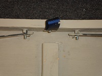
- With the leg pair still clamped tight against the frame, swing the other end of the brace down to about 1” from the deck bottom and mark where the other hole in the brace is on the frame. Drill a small pilot hole through the frame at that point. From the outside of the frame, drill a 5/8” hole about 1/8” into the frame, then enlarge the pilot hole through the frame with a ¼” bit. Insert the carriage bolt, making sure the hole drilled in the bolt is perpendicular to the brace, tap it into the hole to set it, slide the flat washer and the lock washer onto the bolt, screw on and tighten the hex nut. Slide the metal brace onto the bolt and secure with the hitch pin. (Figure 13)
- Unlatch the leg braces and rotate them to their flush, storage position.
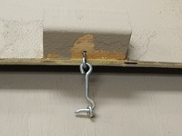
- Finally, screw and glue an extra 2” x 2” glue block to the spreader bar of the inner leg pair and screw in the eye for the gate hook. Drill a hole in the module deck and screw in the gate hook so that it will align with the eye bolt on the spreader bar. Position it so that, when secured, the hook will hold the legs tight against the frame. (Figure 14)
It is highly recommended that once it is assembled, the entire undercarriage of the module be painted to seal
the wood and prevent future warping. Some of the pictures in this article were taken of an old 4’ module that
was stripped down and re-built. Since the old frame already had 2x2 glue blocks in the corners, we couldn’t
install 2x4 glue blocks to space out the inner legs. Instead, we inserted a temporary spacer and then glued and
screwed a second 2x2 glue block as the stabilizer block for the inner legs.
