


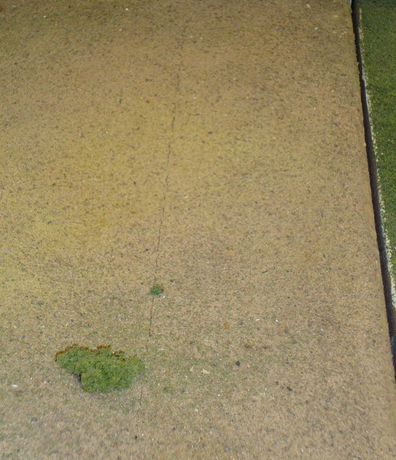
Figure 1 -
Cracks where
wood meets foam.

Figure 2 - Block set |

Figure 3 - Foam |

Figure 4 - Foam cutout made and cleaned |
You can solve this cracking problem and provide adequate support beneath the joiner track area by still using a piece of 1” x 4” hardwood, but making it only 4” long and rotating it 90°. Cover the entire module top with foam, then center the 4” long piece of wood under the yellow (middle) line at each end of the module. (Figure 2) Since dimensional lumber 1” x 4”s are actually ¾” thick and 3½” wide, this placement will make the piece of wood extend forward and back 1¾” from the center of the yellow line, which is sufficient to underlie both the red (front) line and the blue (rear) line. (Figure 3) With a sharp knife, cut the foam along the edges of the lumber, remove the cut block of foam, (Figure 4) and glue and screw the piece of wood in its place. (Figure 5 & 6) Obviously, if your foam is of a different thickness than ¾” you will need to use an equivalently thick piece of wood. (Figure 7) |

Figure 5 - Wood block glued into cutout area. |

Figure 6 - Wood block glued and screwed in place |

Figure 7 - Side view of wood block in place. |
| The red and blue line’s cork roadbed will overlap the seam between the wood and the foam and will hide any cracks that occur due to expansion and contraction. (Figure 8 & 9) You can then proceed with track ballasting as normal. (Figure 10 & 11) When it’s time to install joiner tracks, you will have a firm piece of hard wood where you are pressing down with you joiner tool and will not have to worry about damaging the foam. |

Figure 8 - Cork roadbead glued in place. |

Figure 9 - Cork overlaps wood-foam interface. |

Figure 10 - Ballasted. |

Figure 11 - Finished and ballasted. Wood block cannot be seen. |